March
28, 2024
by Jean-François
Simon
Want to save money while extending the life of your electronic equipment?
Repair your own tools and equipment! From mastering essential tools
to explaining common component faults, this handy guide to electronic
equipment repair will help to boost your confidence as you repair
your devices.
Want to save money while extending the life of your electronic
equipment? Repair your own tools and equipment! From mastering
essential tools to explaining common faults, this handy guide
to electronic equipment repair will help to boost your confidence
as you repair your devices.
First, let's take a look at the tools that will be useful for
most electronic repairs. Of course, everyone will have their list
of favorite tools, according to personal preference. Here's
my list. If you're a beginner, it may give you a few pointers
to get you started. If you've only got one or two of these tools,
and the list seems far too long or far too expensive, don't
panic! On the one hand, it's always possible to do without,
until you've decided that it's the right time to buy a new
tool, and, on the other hand, most of these things can be found
either very cheaply in China, or at affordable prices on the second-hand
market in any country.
Let's start with the essential tools (Figure 1).
You'll need at least: a multimeter, a soldering iron and solder,
an oscilloscope, and an adjustable power supply. To check solder
joints and inspect the PCB for defects, a small magnifying glass
with a high enough magnification (10x— in my case) will be a precious
help. Even a very inexpensive magnifier will be infinitely better
than no magnifier at all; personally, I use a €3 plastic model
from RS (ref 136-8106) which serves me well.
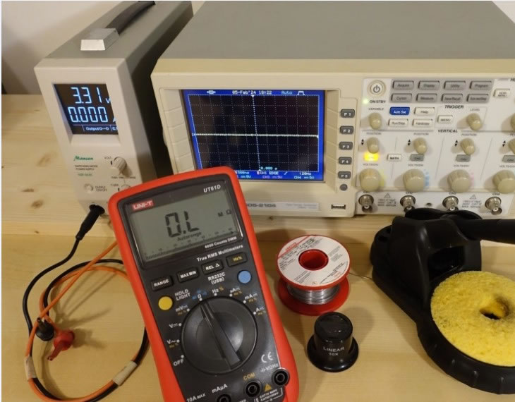
Figure 1: Essential tools.
It's
debatable, but, in my opinion, a second multimeter and a second
soldering iron are also essential tools. Two multimeters are useful
at the same time, among other things for testing power supplies,
by monitoring the output voltage while increasing output current.
As for the second soldering iron, it will be almost irreplaceable
as a complement to the first, for desoldering all kinds of SMD components
with one iron in each hand.
Speaking of soldering, here are a few extra supplies. Desoldering
braid (I recommend the tinned variant) and gel flux. For cleaning
up after soldering, cotton swabs and 99% (or, failing that, 90%)
isopropyl alcohol work well. I'd recommend putting the alcohol
in small plastic bottles (50 or 100 ml, for example), allowing
small quantities to be applied, and to devote one of these bottles
to a 50% isopropyl/50% acetone mixture -- very effective for hard-to-remove
residue. Of course, if you can afford it, a professional cleaner
such as Fluxclene is fine, but not essential. To remove severe corrosion
caused by water ingress or electrolyte leakage from a capacitor,
a fiberglass pencil brush comes in very handy.
Optional Tools to the Rescue
You can do
without them, but once you've bought them, they turn out to
be really useful. I recommend an inexpensive desoldering station.
It's so effective for cleanly and quickly desoldering transistors,
capacitors, DIP ICs, connectors, relays, etc., that I think it
would be a pity to go too long without one, especially with products
as affordable as the ZD-915 or ZD-8915 models under €100. I
would add to this category: an ESR or LCR meter, as well as a
very cheap component tester such as the T4 model.
A Dim Bulb Current Limiter?
In the category
of small, home-made tools that you build up over the course of
your life, I'd also mention a dim bulb current limiter. It's
especially useful when repairing mains power supplies, particularly
when these have faults such as short-circuited diode bridges or
shorted transistors on the primary circuit, a blown fuse, etc.
After repair, it's a good idea to limit the maximum current,
in case we've forgotten something, to prevent the same components
from burning out again.
The principle is very simple: Put an incandescent bulb, with the
appropriate voltage for mains power wherever you are on the planet,
in series with one of the two power supply wires. In the event
of a problem (at worst, a short circuit between live and neutral),
there will be no more explosions; the lamp will simply light up,
giving you time to disconnect without damage.
It's a good idea to have several lamps of different wattages,
so as to be able to limit the current to a higher or lower value,
depending on the device you wish to test. This can be done very
simply with a few spare bulbs and a bulb socket; you simply screw
in the bulb of your choice as needed. Note that you need an incandescent
bulb, not a CCFL or LED; to find one, you'll maybe have to use
the classified ads, as these have completely disappeared from
store shelves in many countries.
For my part, I made a slightly more complicated setup than necessary
(Figure 2), using a rotary switch to connect a number
of small halogen bulbs in parallel (20 W 230 V,
G9), enabling me to limit the current in five steps -- from 80 mA
to around 400 mA.
Now, let's talk about repair methods. Here are a few things
you might find helpful.
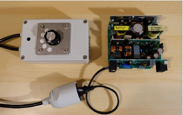
Figure 2:
A home-made current limiter.
How to Tackle Electronic Repairs: A Few Hints
Start by taking stock of the situation. Do you know exactly what
the fault is? If it's a device you own, or one you were using
yourself when the fault occurred, you probably have a pretty good
idea. But take the time to make a note of it, noting anything that
might be a clue. Does the unit have a display that indicates an
error message? Does it run when cold and stop after warming up?
Or vice versa? Has the unit suffered a shock? Does lightly tapping
it affect its operation? All these clues will help you get started,
so don't overlook them. If possible, try to observe the fault
yourself, if it's a repair you're doing for someone else.
Have a look on the internet to see if anyone else, in any forum,
might have had the same problem on the same device. See if a service
manual or schematics are available.
Next comes disassembly. Remember to take photos to make reassembly
easier, and number the connectors on the cables with a fine-tipped
permanent marker if necessary, so you can reattach them unambiguously
on reassembly.
Two Past Repairs
Once, I troubleshot a Lithium battery-powered remote control
for industrial equipment that refused to work. Everything on the
board seemed to be inactive. No power, no reaction to button presses,
even when replacing the battery with a power supply. In fact,
a simple visual check revealed the solution: The central pin of
the connector used to charge the battery was broken. As a result,
the battery had discharged, and the battery charging/monitoring
IC had put the whole board into deep sleep. To unlock this protection,
you need to charge the battery, not with a lab power supply, but
with the IC in question, which couldn't happen with the pin
missing. Keep your eyes open!
Another time, there was a rather complex motor controller which
displayed “emergency stop switch engaged,� although this was
not the case. I identified the terminal block dedicated to the
emergency stop by consulting the manual, and followed the tracks
back to one of the board's microcontrollers, a good twenty centimeters
away, checking numerous components along the way. I finally found
a short-circuited transistor, just before the signal reached the
microcontroller. Victory! This €1,500-plus device was finally
repaired by replacing this 20-cent component.
Visual Inspection Comes First
For diagnosis, start with a good visual check:
I've lost count of the number of times this has been able to
tell me immediately, if not the precise fault, then at least its
location on the PCB, thanks to burnt-out components, signs of
overheating, missing components (component leads sometimes snap
on impact, after having been fatigued by thermal cycling), cracked
solder joints, and so on. Use your other senses too: a suspicious
smell? A strange noise when you shake the case?
Try to identify functional blocks. Power supplies, front panel
PCBs, digital control section, analog section, output stages if
any, etc. Use deduction to locate possible sources of trouble.
Choose a direction: Either in the direction of flow (energy flow
or information flow), or against the flow. From inputs to outputs,
or vice versa. There are no hard and fast rules; at the beginning,
you can choose arbitrarily, and alternate between the two techniques
as the diagnosis progresses. For a power supply that doesn't
light up at all, it's often convenient to start from the mains
input, and check one after the other in the chain: fuse OK, diode
bridge OK, PFC transistor OK, etc. On the other hand, if the power
supply powers on but there's a fault on just one of its multiple
outputs, then it's more relevant to start looking at the output,
working backwards.
Is the Power On?
As a general rule, start by checking the power supply rails.
Sometimes, there may be test points; otherwise, you can measure
the voltage across the electrolytic capacitors. Common voltages
are 12 V, 5 V, 3.3 V, etc. A fluctuating or absent
voltage will alert you to a possible fault.
If the power supplies seem to be working, check that the functional
blocks you come across are also powered, by measuring the voltages
at the power supply terminals of the integrated circuits and microcontrollers.
Datasheets and experience will tell you which pin numbers to look
out for. In the event of zero voltage, use an ohmmeter to check
that the rail is not short-circuited to ground. If it is, look
for the short circuit; if it isn't, look upstream to find out
why the power supply isn't turned on.
Whenever possible, I try to desolder as few components as possible.
Nevertheless, it often happens that there's a doubt, and you
have to desolder a component to confirm a measurement, especially
when looking for short-circuits. Beware! I've often come across
PCBs without silk-screening, and it can happen to anyone to accidentally
solder a SO-8 or SO-14 integrated circuit rotated, leading to
anger and frustration on the next test. Refer to the photos taken
beforehand.
In this phase of troubleshooting, it's likely that you'll
have to alternate frequently between in-circuit component testing
(without power), desoldering, re-soldering, possibly swapping
components, testing with power on, and so on. In all cases, take
your time and keep a clear head. Above all, never solder or desolder
on a live circuit! And make sure it doesn't happen either by
accident. Apart from the safety issue, there's a very real risk
of creating faults by short-circuiting two adjacent pads with
the iron.
Measuring Safely
Never take oscilloscope measurements on the primary side (mains
side, before the transformer) of a power supply, unless you are
fully informed and fairly experienced with differential probes
and isolation transformers. On the secondary side, there are fewer
safety risks, but still a risk of creating faults. Rather than
taking the chance of slipping with the probe tip, I often prefer
to solder a small piece of wire to the node of interest, and hook
the probe to it. Another option is to use good quality, thin mini-grabbers,
like the ones from EZ-Hook (see Figure 3). This leaves
my hands free to operate the on/off button and the oscilloscope
controls.
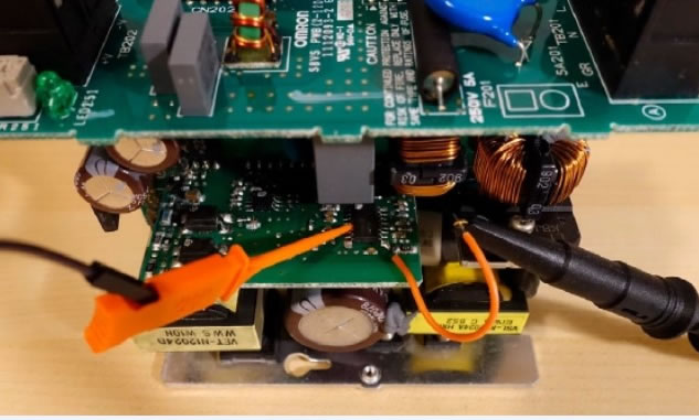
Figure 3: How to safely probe circuits for live testing.
When
I worked in an electronics repair shop, I used my computer all the
time to look for the datasheets and pinouts of the countless new
components I didn't know about when repairing a particular device.
When working without schematics, which are rarely available, and
sometimes on PCBs without a silkscreen, SMD marking catalogs are
invaluable tools to identify components. "SMD Marketing
Codes" and "SMD
Codebook" are two well-known examples, and there are
others too.
Finally, there comes the moment when you've found a faulty component.
No doubt, your measurements are categorical: It's burnt out. Congratulations!
Search the surrounding area, on all the tracks leading from all
the pads of that component for any other damage.
Replacing Components
To
replace the component, try as far as possible to replace it with
an identical one, by searching all the usual suppliers: Farnell,
RS, Mouser, Digikey, Distrelec, etc. If possible, avoid eBay and
Aliexpress, where the probability of receiving a counterfeit component
is sometimes as high as 100%.
If the component is difficult to source or obsolete,
there is no choice but to find an equivalent. Pay attention to
the type of package, its pinout, as well as the main characteristics:
maximum voltage and current for transistors, switching speed,
and so on. If in doubt, don't hesitate to ask for help in a
forum, where members are generally very helpful and friendly.
In the following section, let's have a look
at a few common faults that can happen for some of the more common
components, as well as a few tips about testing them.
Failure Modes of Common Components
It can be
useful to have an idea of the types of failure that can occur
in a given type of component so that you can search effectively.
It's common to hear that electrolytic capacitors are always
the culprits. This is sometimes true of very inexpensive switch-mode
power supplies, which are built with capacitors limited to 85°C
instead of the slightly more expensive ones that can withstand
105°C. Often, there is very little margin, in terms of both voltage
and capacitance; this excessively strains the capacitors, which
will generally give up and fail just after the expiry of the legal
warranty. However, in better-designed devices, or in test
and measurement instruments and industrial equipment, this is
far from being the general case. Here's a list of common failures,
classified by component type.
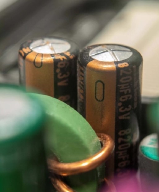
Figure 4: The infamous bulging electrolytic capacitors. (Source:
Wikipedia)
Electrolytic capacitors: Sometimes bulging, as shown in Figure 4,
or having lost electrolyte, lost capacitance or having an ESR value
too high. Test with a multimeter in capacitor mode, an ESR meter,
or an LCR meter. Those that are bulging or have leaked need to be
replaced without further testing; for those with a normal appearance,
desolder one lead to prevent neighboring components from interfering
with the measurement.
Power transistors (bipolar or MOSFET): Often short-circuited,
sometimes open-circuited. Test with multimeter diode mode. Identify
the pinout first. For a bipolar transistor, check the base-emitter
and base-collector junctions. Also check that there is no continuity
between collector and emitter. For a MOSFET, check that the MOSFET's
internal diode is visible (junction voltage around 0.5 or 0.6 V)
between Drain and Source (Figure 5), and that the gate
is isolated from the other two pins.
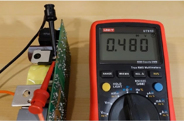
Figure 5:
Using the diode mode to test a power MOSFET.
Power diodes, rectifier diode bridges: Often short-circuited,
more rarely open-circuited. When tested in diode mode, you should
find a voltage of around 0.6 or 0.7 V for conventional diodes
in the forward direction, and OL (infinity) in the reverse direction.
For Schottky diodes, the voltage is lower, down to around 0.3 V
Power resistors: Often open. Typical case: resistors
used to limit the start-up current of some switch-mode power supplies.
Through-hole or SMD diodes, or Zener diodes, and small
bipolar or MOSFET transistors: Short-circuited or open-circuited.
Test them using the Diode mode.
Power ICs: Meaning those which can potentially
dissipate some heat, such as motor drivers: Supply pins short-circuited
to ground, or output pins short-circuited to ground or VCC. This
is often the case with switching-controller ICs, on the primary
side of switching power supplies. In particular, those incorporating
the control logic and power transistor in the same package (such
as ST's VIPER20 and others) are fragile.
Plastic film capacitors: Loss of capacitance. More
rarely, short-circuited. Capacitance loss is frequent, especially
when these capacitors are used as capacitive droppers, i.e., to
obtain a voltage of a few volts to supply a logic circuit from the
mains. In this case, a constant AC current flows permanently through
the capacitor, which will age prematurely.
Transformers: Open-circuit, or short-circuit between
turns (leading to overcurrent and overheating).
Through-hole or SMD resistors: Sometimes visibly
burnt out, sometimes open-circuited, not visible to the naked eye.
That can be checked easily with an ohmmeter: Due to the various
components in parallel with the resistor under test, the resistance
measured must always be lower than the value shown on the resistor
marking. If this is not the case, the resistor is open-circuited
or has drifted upwards considerably.
SMD ceramic capacitors: Sometimes short-circuited.
In this case, the entire supply rail is shorted to ground. To locate
it on the board, you can use a lab power supply. Set the voltage
to a low value, such as 1 V or 2 V, and the maximum current
to about 1 A. Connect it to the power rail, while respecting
the polarity. This will force current into the short-circuit. Then,
use the DMM in millivoltmeter mode to get closer and closer to the
short-circuit. The voltage is lowest across the short-circuited
capacitor. Some people recommend using a beefier power supply and
setting the current to a higher value; this can make the short-circuited
component warm up, and it can then be seen with a thermal camera.
If you use this technique, be careful, a higher current could also
burn some tracks instead. In very rare occasions, these caps can
also go open circuit -- see the text frame about the power supply
for an example.
Relays: Their contacts can become resistive after
a large number of actuations. This can be checked with the ohmmeter
on the contacts, by supplying the relay coil with the appropriate
voltage from a lab power supply. Take care to use the correct voltage
for the coil, and the correct polarity, to avoid damaging the rest
of the circuit. The (+) can usually be found by looking at which
of the two coil terminals is connected to the cathode of the freewheeling
diode, which is often located nearby. If in doubt, unsolder the
relay to test it safely outside the circuit.
Push-buttons: Sometimes short-circuited (causing
erratic device operation), or sometimes no longer making any contact
(the device no longer responds), especially when they have been
in contact with water.
Solder joints: Some lead-free alloys are prone
to cracking with age, as a result of repeated thermal cycling. These
can be hard to see with the naked eye, but a hair-thin crack can
be enough to break continuity completely. This shows the importance
of inspecting the entire board with a magnifying glass. An example
of rather big cracks is visible in Figure 6.
Other, much thinner, ones are much harder to find
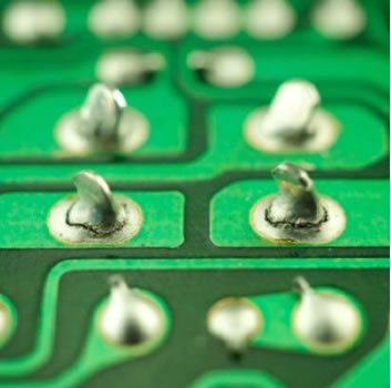
Figure 6: These solder joints have seen better days.
Quartz
crystals: They are generally reliable, but may stop oscillating
after a shock. If the microcontroller to which a quartz is connected
is active, with some LEDs flashing or something showing on the LCD,
you know the crystal is working. If no such activity is visible,
the easiest way is to probe one of its terminals with an oscilloscope,
relative to ground. Then move the probe to the second terminal.
You should find a stable oscillation, at least a few hundred millivolts
in amplitude, at the frequency marked on the quartz. One of the
signals will have a larger amplitude than the other -- this is
normal.
Note: An 10× probe should be used for this to avoid disturbing
the oscillation too much. Sometimes, the input capacitance of the
oscilloscope probe stops the oscillation of a quartz crystal, even
though the quartz is fine. In this case, try again on the second
terminal: This time, you should see an oscillation. Oscillators
often have an input side with a high impedance, on which this can
occur. The output side, with its lower impedance, is less easily
disturbed. If you don't see anything on any of the terminals,
either the microcontroller is not powered on or the quartz is defective.
Other faults: In an industrial electronics repair shop, we
come across failures that are a little different from those encountered
in consumer electronics. For example, liquid damage is very common,
due to water penetration when machines are washed. As the equipment
is often live, with high voltages (400 V AC) and circuit
breakers rated for substantial currents, the damage can be severe.
I often encountered burn marks, vaporized tracks/wires/connectors,
open NTC thermistors, short-circuited MOVs, as well as severe oxidation
on tracks, pads and components. Finally, connectors were often oxidized,
or caused poor contacts, having become loose due to vibration. This
frequently leads to arcing between adjacent pins.
Electronic Equipment Repair: Looking Ahead
Now you should
be able to approach repairs with more confidence and serenity. I
strongly encourage you to give it a go -- the results and the satisfaction
you'll derive from them are well worth the effort. Also, don't
hesitate to check out the forums and YouTube, where you'll find
some very interesting content. Each of the electronics specialists
on YouTube has their own personality and their own, often different,
methods -- that's what makes it so rich. For example, when
it comes to repairing test and measurement instruments, some videos
from The
Signal Path, or Feedback
Loop, are inspiring; when it comes to switching power
supplies, DiodeGoneWild
produces videos packed with information; and finally, for retro
computing enthusiasts, take a look at Tony359's
videos. Good luck with your repairs, and have fun!
A Power Supply That Wouldn't Cooperate
That one gave
me a hard time. I troubleshot an ATX PC power supply, a CX400 from
Corsair, dating from the 2010s. It was shutting down after some
time. The first problem was that the power supply was willing to
switch on in the PC, but categorically refused to start up on my
workbench when I used the classic technique of shorting the green
PS_ON wire to ground, which complicated my diagnosis. Being less
experienced at the time, I didn't immediately think of connecting
an additional resistive load on the 5V_SB rail (standby supply)
to remedy this.
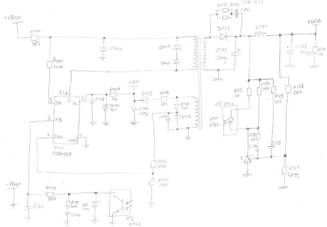
Having done this, I noticed considerable instability in the 5V_SB
voltage, with sawtooth fluctuations of several volts in amplitude.
Yet all the infamous electrolytic capacitors were in good condition
on the output (and on the other outputs too). To help me troubleshoot,
I made a hand-drawn snippet of schematic, as shown opposite. I highly
recommend you do the same when you get stuck; schematics, even incomplete
and hand-drawn, are always helpful.
In fact, there was a small SMD ceramic capacitor, C107 on the previous
figure, which was part of an RC low-pass filter, in the voltage
feedback loop of this rail. This capacitor had gone open, and was
no longer filtering anything, causing the instability. A very rare
failure! A few years later, while browsing a forum, I came across
someone who'd had the same problem, with the same component in
the same power supply. That was probably a manufacturing defect
that caused the capacitor to crack due to thermal cycling.
A Few Additional Tips and Tricks
- Use
the sharpest probe tips possible, to overcome the oxidation
layer on solder joints and make reliable measurements on components
without having to press too hard. This reduces the risk of slipping.
Cheap multimeter probe tips are often made of plated brass and
tend to dull quickly. For my part, I use Hirschmann PRUEF 2
stainless steel tips. They are very sharp, and I regularly re-sharpen
them on a small whetstone.
- When
component markings are made difficult to read by a thick clear
varnish, called "conformal coating," acetone
can often be used to remove it and see more clearly. Use cotton
swabs and a hard wooden tool such as a chopstick to scrape.
Don't use a metal tool, which will scratch the surface of
the component and make it even more difficult to read the marking.
- Some
switch-mode power supplies require a minimum load to operate.
A suitable power resistor will do, but is not always included
on the PCB itself. Think about this if the power supply you're
troubleshooting can't start up or fails to regulate its output
voltage properly.
- Sometimes,
before being wave-soldered, SMD components are glued with a
dot of red glue to hold them when they're upside-down. They
are tricky to desolder without damaging the component and the
pads. Heat all the terminals at the same time with a large soldering
tip and plenty of solder. For small 2-terminal components, a
“knife� tip can work well to heat both sides simultaneously.
For bigger components, use two soldering irons. While heating,
gently insert an X-ACTO blade under the component to detach
the glue.
- Beware
of charged capacitors! In particular, bulk capacitors on the
primary side of switch-mode power supplies are often charged
to 325 V DC. There is sometimes a dedicated resistor to discharge
them when the mains is switched off, but not always. Before
any test or measurement, check with a multimeter that they are
completely discharged, and discharge them if necessary. I use
a pair of multimeter probes connected together via a 2.7 kΩ
/ 5 W resistor, as shown in the photo opposite. Don't do this
with a screwdriver, as it will damage the screwdriver, the solder
joint and also the capacitor due to the sudden current spike.
- To
open snap-on enclosures made of plastic, don't use a screwdriver,
as it leaves dents in the plastic. You can buy dedicated spudgers
which are wider, and thin and flexible, to avoid marking. I
use an old paring knife from my kitchen, which I purposely de-sharpened
completely with sandpaper, to make it totally harmless.
- Leaded
solder can be easier to use to prototype new circuits and general
DIY work, and I try to use it whenever possible. It can be difficult
to buy due to RoHS restrictions, though. Note that mixing leaded
and lead-free when reworking a solder joint yields poor results
and should be avoided. Either buy a roll of each, or carefully
remove all the lead-free solder residue before re-soldering
with the leaded alloy. In any case, choose a good brand, such
as Loctite, Kester, Stannol, etc. from a well-known retailer;
avoid unknown brands from AliExpress.
Editor's note:
This article appeared in Elektor May/June 2024. |


 MW list